Tag Archives: pulley pulley

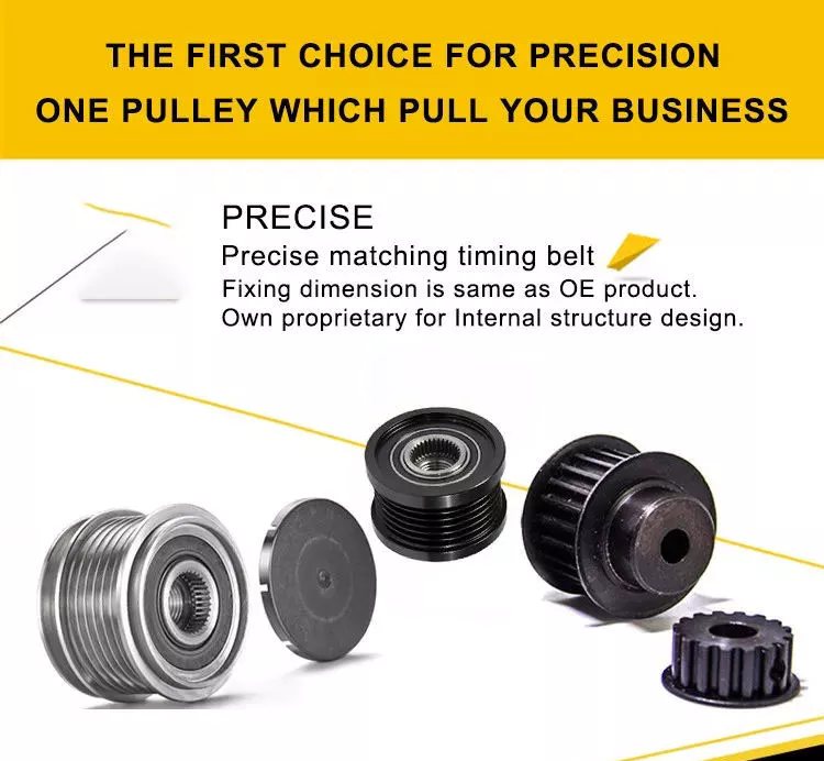
China Processing nylon synchronous pulley plastic pulley POM gear polyformaldehyde Timing Nylon Pulleys agricultural parts UK

Warranty: 3 years
Applicable Industries: Manufacturing Plant
Customized support: OEM
Type: TIMING
Material: ALLOY
Product name: Timing Belt Pulley
Color: natural oxidation
tooth type: XL L H 3M 5M 8M 14M
pitch: 5.08
Bore Type: round hple
packaging: Manufacturing Plant
Surface treatment: Anodized
OEM: OEM Services Provided
Standard or Nonstandard: Standard
Certification: EPA
Packaging Details: wood box

Products Description

Item Name Synchronous wheel
volumeCalculate according to drawing
WeightCalculate according to drawing and material
ColorBlack white red green .etc
Material Carbon steelAluminum alloybrassStainless steelnylonAnd other materials
Working temperatureThe natural temperature
processGear hobbing, gear shaper, powder metallurgy
Nylon synchronizing wheelMaterial: nylonTooth type: 2M/ S2m 3M/ S3m 5M/ S5m 8M/ S8m 14M/ S14m 20M/ S20mT2.5 AT5 / T5 AT10 / T10 AT20 / T20MXL XL L H XH XXHShape: A type B typeSpecial shape: can be made to order Nylon timing beltMaterial: nylon POM PP Tooth type: 2M/ S2m 3M/ S3m 5M/ S5m 8M/ S8m 14M/ S14m 20M/ S20mT2.5 AT5 / T5 AT10 / T10 AT20 / T20MXL XL L H XH XXHShape: A type B typeSpecial shape: can be made to order Company Profile HangZhou DORING e- commerce co., LTD., is specialized is engaged in the transmission of product traders and manufacturers, we are synchronous wheel, synchronous belt, round wedge, the wedge belt, flat belt and conveyor belt,transmission belt, coupling, when tight set, sprocket, gear, etc., all of our products comply with international quality standards, are very popular in a variety of different market. If you are interested in our products or need to customize products, please feel free to contact us. We look forward to in the near future with friends from all over the world to establish a successful partnership. Q1.Can I have a sample order for Timing belt?Yes, we welcome sample order to test and check quality. Mixed samples are acceptable.Q2. What about the lead time?Sample needs 3-5 days, mass production time needs 2-3 weeks for order quantity.Q3. Do you have any MOQ limit for belt order?Low MOQ, 1pc for sample checking is availableQ4. Is it OK to print my logo on belt product?Yes. Please inform us your logo or design before mass productionQ5.What is your company major products?Our main products are Sausage Timing Belt ,film pull belt ,rubber belt, transmission belt,triangle V belt and wheels etc.Q6.What about the price?We try our best to give the competitive price with the high quality goods.

When your axle needs to be replaced

If you’re wondering when your axle needs to be replaced, you should be aware of these signs first. A damaged axle is usually a sign that your car is out of balance. To tell if the axle needs to be replaced, listen for the strange noise the wheels make as they move. A rhythmic popping sound when you hit bumps or turns indicates that your axle needs to be replaced. If this sounds familiar, you should visit a mechanic.
Driveshaft

Symptoms of a broken shaft

You may notice a clicking or clanking sound from the rear of the vehicle. The vibrations you feel while driving may also indicate damaged axles. In severe cases, your car may lose control, resulting in a crash. If you experience these symptoms, it’s time to visit your auto repair shop. For just a few hundred dollars, you can get your car back on the road, and you don’t have to worry about driving.
Often, damaged axles can be caused by a variety of causes, including poor shock or load bearing bearings. Other causes of axle problems can be an overloaded vehicle, potholes, or a car accident. A bad axle can also cause vibrations and power transmission failures while driving. A damaged axle can also be the result of hitting a curb or pothole. When shaft damage is the cause of these symptoms, it must be repaired immediately.
If your car’s front axle is bent, you may need to replace them at the same time. In this case, you need to remove all tires from the car, separate the driveshaft from the transmission, and remove the axle. Be sure to double check the alignment to make sure everything is ok. Your insurance may cover the cost of repairs, but you may need to pay a deductible before getting coverage.
Axle damage is a common cause of vehicle instability. Axles are key components of a car that transmit power from the engine to the wheels. If it breaks, your vehicle will not be able to drive without a working axle. Symptoms of damaged axles can include high-speed vibrations or crashes that can shake the entire car. When it breaks down, your vehicle won’t be able to carry the weight of your vehicle, so it’s important to get your car repaired as soon as possible.
When your axle is damaged, the wheels will not turn properly, causing the vehicle to crash. When your car has these problems, the brakes won’t work properly and can make your car unstable. The wheels also won’t line up properly, which can cause the brakes to fail. Also, a damaged axle can cause the brakes to become sluggish and sensitive. In addition to the obvious signs, you can also experience the sound of metal rubbing against metal.

Types of car axles

When you’re shopping for a new or used car, it’s important to know that there are different types of axles. Knowing the year, make, model, trim and body type will help you determine the type you need. For easy purchasing, you can also visit My Auto Shop and fill out the vehicle information checklist. You can also read about drivetrains and braking systems. After mastering the basic information of the vehicle, you can purchase the axle assembly.
There are two basic types of automotive axles: short axles and drive axles. The axle is the suspension system of the vehicle. They carry the drive torque of the engine and distribute the weight throughout the vehicle. While short shafts have the advantage of simpler maintenance, dead shafts are more difficult to repair. They’re also less flexible, which means they need to be durable enough to withstand harsh conditions.
Axles can be one of three basic types, depending on the weight and required force. Semi-floating shafts have a bearing in the sleeve. They attach to the wheel and spin to generate torque. Semi-pontoons are common in light pickup trucks and medium-duty vehicles. They are not as effective as floating axles, but still provide a solid foundation for wheel alignment. To keep the wheels aligned, these axles are an important part of the car.
The front axle is the largest of the three and can handle road shocks. It consists of four main parts: stub shaft, beam, universal pin and track rod. The front axle is also very important as it helps with steering and handling road shocks. The front axle should be strong and durable, as the front axle is most susceptible to road shocks.
Cars use two types of axles: live and dead. Live axles connect to the wheels and drive the vehicle. Dead axles do not drive the wheels and support the vehicle. Those with two wheels have live axles. Heavy trucks and trailers use three or more. The number of axles varies according to the weight and load of the vehicle. This will affect which type of axle you need.
Driveshaft

life expectancy

There are a few things to keep in mind when determining the life expectancy of an automotive axle. First, you should check for any signs of wear. A common sign is rust. If your vehicle is often driven in snow and ice, you may need to replace the axle. Also, you should listen for strange sounds from the wheels, such as rhythmic thumping.
Depending on the type of axle, your car may have an average lifespan of 70,000 miles. However, if you have an older car, the CV axles probably won’t last five years. In this case, you may wish to postpone the inspection. This way, you can save money on repairs. However, the next step is to replace the faulty CV shaft. This process can take anywhere from one hour to three hours.
Weaker axles will eventually break. If it were weakened, it would compromise the steering suspension, putting other road users at risk. Fortunately, proper maintenance will help extend the life of your axle. Here are some tips for extending its lifespan. A good rule of thumb is to never go over speed bumps. This will cause sudden breakage, possibly resulting in a car accident. To prolong the life of your vehicle’s axles, follow these tips.
Another thing to check is the CV connector. If loose, it can cause vibration or even breakage if not controlled. Loose axles can damage the body, suspension and differential. To make matters worse, the guard on the CV joint could tear prematurely, causing the shaft to come loose. Poor CV connections can damage the differential or transmission if left unchecked. So if you want to maximize the life expectancy of your car’s axles, consider getting them serviced as soon as possible.
Driveshaft

The cost of repairing a damaged axle

A damaged axle may need repair as it is responsible for transferring power from the engine to the wheels. A damaged axle can cause a crash or even loss of control. Repairing an axle is much simpler than dealing with an accident. However, damaged axles can cost hundreds of dollars or more. Therefore, it is important to know what to do if you suspect that your axle may have a damaged component.
When your car needs to be replaced or repaired, you should seek the help of a professional mechanic to keep your car safe. You can save a lot of money by contacting a local mechanic who will provide the parts and labor needed to repair the axle. Also, you can avoid accidents by fixing your car as soon as possible. While axles can be expensive, they can last for many years.
The cost of repairing a damaged axle depends on the amount of repairs required and the vehicle you are driving. Prices range from $300 to $1,000, depending on the car and its age. In most cases, it will cost you less than $200 if you know how to fix a damaged axle. For those without DIY auto repair experience, a new axle can cost as little as $500. A damaged axle is a dangerous part of driving.
Fortunately, there are several affordable ways to repair damaged axles. Choosing a mechanic who specializes in this type of repair is critical. They will assess the damage and decide whether to replace or repair the part. In addition to this, they will also road test your car after completing the repairs. If you are unsure about repair procedures or costs, call a mechanic.

China Processing nylon synchronous pulley plastic pulley POM gear polyformaldehyde Timing Nylon Pulleys     agricultural parts UKChina Processing nylon synchronous pulley plastic pulley POM gear polyformaldehyde Timing Nylon Pulleys     agricultural parts UK
editor by czh

China Cable pulley agricultural trailer parts

Type: Flat Belt
Material: Steel
Model Number: BLHC
roller material: nylon or Alu. ally
color: optional
Packaging Details: carton, pallet or wooden case
Port: `ZheJiang

Cable pulley
Usage: Used for laying cables, wire rope etc. reducing friction, protecting cable, saving time and effort.
Bearing roller materials can be steel, aluminum, or nylon.
It can be designed with many kinds of appearance and structures according to usage.
Features: light weight, strong bearing, reducing friction, long life
Color: optional

What Is a Worm Gear Reducer?

If you have never seen a worm gear reducer before, you’re missing out! Learn more about these incredible gears and their applications by reading this article! In addition to worm gear reducers, learn about worms and how they’re made. You’ll also discover what types of machines can benefit from worm gears, such as rock crushers and elevators. The following information will help you understand what a worm gear reducer is and how to find one in your area.
worm shaft

Typical worm shaft

A typical worm has two shafts, one for advancing and one for receding, which form the axial pitch of the gear. Usually, there are eight standard axial pitches, which establish a basic dimension for worm production and inspection. The axial pitch of the worm equals the circular pitch of the gear in the central plane and the master lead cam’s radial pitch. A single set of change gears and one master lead cam are used to produce each size of worm.
Worm gear is commonly used to manufacture a worm shaft. It is a reliable and efficient gear reduction system that does not move when the power is removed. Typical worm gears come in standard sizes as well as assisted systems. Manufacturers can be found online. Listed below are some common materials for worm gears. There are also many options for lubrication. The worm gear is typically made from case hardened steel or bronze. Non-metallic materials are also used in light-duty applications.
A self-locking worm gear prevents the worm from moving backwards. Typical worm gears are generally self-locking when the lead angle is less than 11 degrees. However, this feature can be detrimental to systems that require reverse sensitivity. If the lead angle is less than four degrees, back-driving is unlikely. However, if fail-safe protection is a prerequisite, back-driving worm gears must have a positive brake to avoid reverse movement.
Worm gears are often used in transmission applications. They are a more efficient way to reduce the speed of a machine compared to conventional gear sets. Their reduced speed is possible thanks to their low ratio and few components. Unlike conventional gear sets, worm gears require less maintenance and lower mechanical failure than a conventional gear set. While they require fewer parts, worm gears are also more durable than conventional gear sets.
There are two types of worm tooth forms. Convex and involute helicoids have different types of teeth. The former uses a straight line to intersect the involute worm generating line. The latter, on the other hand, uses a trapezoid based on the central cross section of the root. Both of these tooth forms are used in the production of worms. And they have various variations in pitch diameter.
worm shaft

Types of worms

Worms have several forms of tooth. For convenience in production, a trapezoid-based tooth form is used. Other forms include an involute helicoidal or a convolute worm generating a line. The following is a description of each type. All types are similar, and some may be preferred over others. Listed below are the three most common worm shaft types. Each type has its own advantages and disadvantages.
Discrete versus parallel axis: The design of a worm gear determines its ratio of torque. It’s a combination of two different metals – one for the worm and one for the wheel – which helps it absorb shock loads. Construction equipment and off-road vehicles typically require varying torques to maneuver over different terrain. A worm gear system can help them maneuver over uneven terrain without causing excessive wear.
Worm gear units have the highest ratio. The sliding action of the worm shaft results in a high self-locking torque. Depending on the angle of inclination and friction, a worm gear can reach up to 100:1! Worm gears can be made of different materials depending on their inclination and friction angle. Worm gears are also useful for gear reduction applications, such as lubrication or grinding. However, you should consider that heavier gears tend to be harder to reverse than lighter ones.
Metal alloy: Stainless steel, brass, and aluminum bronze are common materials for worm gears. All three types have unique advantages. A bronze worm gear is typically composed of a combination of copper, zinc, and tin. A bronze shaft is more corrosive than a brass one, but it is a durable and corrosion-resistant option. Metal alloys: These materials are used for both the worm wheel.
The efficiency of worm gears depends on the assembly conditions and the lubricant. A 30:1 ratio reduces the efficiency to 81:1%. A worm gear is more efficient at higher ratios than an helical gear, but a 30:1 ratio reduces the efficiency to 81%. A helical gear reduces speed while preserving torque to around 15% of the original speed. The difference in efficiency between worm gear and helical gear is about half an hour!

Methods of manufacturing worm shafts

Several methods of manufacturing worm shafts are available in the market. Single-pointed lathe tools or end mills are the most popular methods for manufacturing worms. These tools are capable of producing worms with different pressure angles depending on their diameter, the depth of thread, and the grinding wheel’s diameter. The diagram below shows how different pressure angles influence the profile of worms manufactured using different cutting tools.
The method for making worm shafts involves the process of establishing the proper outer diameter of a common worm shaft blank. This may include considering the number of reduction ratios in a family, the distance between the worm shaft and the gear set center, as well as the torques involved. These processes are also referred to as ‘thread assembly’. Each process can be further refined if the desired axial pitch can be achieved.
The axial pitch of a worm must match the circular pitch of the larger gear. This is called the pitch. The pitch diameter and axial pitch must be equal. Worms can be left-handed or right-handed. The lead, which refers to the distance a point on the thread travels during one revolution of the worm, is defined by its angle of tangent to the helix on the pitch of the cylinder.
Worm shafts are commonly manufactured using a worm gear. Worm gears can be used in different applications because they offer fine adjustment and high gear reduction. They can be made in both standard sizes and assisted systems. Worm shaft manufacturers can be found online. Alternatively, you can contact a manufacturer directly to get your worm gears manufactured. The process will take only a few minutes. If you are looking for a manufacturer of worm gears, you can browse a directory.
Worm gears are made with hardened metal. The worm wheel and gear are yellow in color. A compounded oil with rust and oxidation inhibitors is also used to make worm gears. These oils adhere to the shaft walls and make a protective barrier between the surfaces. If the compounded oil is applied correctly, the worm gear will reduce the noise in a motor, resulting in a smoother performance.
worm shaft

applications for worm gear reducers

Worm gears are widely used in power transmission applications, providing a compact, high reduction, low-speed drive. To determine the torque ratio of worm gears, a numerical model was developed that makes use of the equation of displacement compatibility and the influence coefficient method, which provides fast computing. The numerical model also incorporates bending deflections of the gear surfaces and the mating surfaces. It is based on the Boussinesq theory, which calculates local contact deformations.
Worm gears can be designed to be right or left-handed, and the worm can turn either clockwise or counter-clockwise. An internal helical gear requires the same hand to operate both parts. In contrast, an external helical gear must be operated by the opposite hand. The same principle applies to worm gears in other applications. The torque and power transferred can be large, but worm gears are able to cope with large reductions in both directions.
Worm gears are extremely useful in industrial machinery designs. They reduce noise levels, save space, and give machines extra precision and fast-stopping capabilities. Worm gears are also available in compact versions, making them ideal for hoisting applications. This type of gear reducer is used in industrial settings where space is an issue. Its smaller size and less noise makes it ideal for applications that need the machine to stop quickly.
A double-throated worm gear offers the highest load capacity while still remaining compact. The double-throated version features concave teeth on both worm and gear, doubling the contact area between them. Worm gears are also useful for low to moderate-horsepower applications, and their high ratios, high output torque, and significant speed reduction make them a desirable choice for many applications. Worm gears are also quieter than other types of gears, reducing the noise and vibrations that they cause.
Worm gears have numerous advantages over other types of gears. They have high levels of conformity and can be classified as a screw pair within a lower-pair gear family. Worm gears are also known to have a high degree of relative sliding. Worm gears are often made of hardened steel or phosphor-bronze, which provides good surface finish and rigid positioning. Worm gears are lubricated with special lubricants that contain surface-active additives. Worm gear lubrication is a mixed lubrication process and causes mild wear and tear.

China Cable pulley     agricultural trailer partsChina Cable pulley     agricultural trailer parts
editor by czh

China AH164868/AH221847 Agricultural machinery Pulley For John Deere Combine gearbox with high quality

Warranty: 3 years
Applicable Industries: Garment Shops, Manufacturing Plant, Machinery Repair Shops, Farms, Home Use, Retail, Construction works, Energy & Mining
Customized support: OEM, ODM, OBM
Type: ROUND BELT
Material: Steel
Product name: Pulley For JD Feed House Parts
Application: Agricultural machinery parts
OEM No: AH164868/AH221847
Weight: 3.63KG
Packaging Details: Wooden Case/Pallet/Plywood Case
Port: ZheJiang / HangZhou

AplicationSpare part for farm machinery drive John Deere.DescriptionMaintains tension in the drive belt from 1 unit to another agricultural machine.For replacement of worn or damaged spare parts during maintenance work.CharacteristicJohn Deere pulley is available online from mower professional. We have a wide range of alternatives to John Deere pulleys.Our online catalog has a large selection of John Deere pulleys that can be delivered directly to your door.

Click here for more details!
Our Main procucts Please click on the photos below to visit their websites.
Company Information FAQ Q:What is the strength of your company?A:We have a engineer team,who have well experienced on products and machine designs.We can help you to solve the problem you meet.Q:How about you quality?A:We have our own prcoessional factory and worker,so believe that our products have advange over our competitors.Q:What is you MOQ?A:Minimum order quality is 1 piece.Q:Could you produce customized product according to your drawing or sample?A:Yes.We have abundant experience in the production of non-standard products. Packing&Shipping Packaging:Chain+Plastic Bag+ Carton+Wooden case( If you have other requirements, we can customized according to customer requirements packaging. )Shipping :1.Most of the standard ones are in stock which we can send in 3-10 days after inspection and package.2. Customized products delivery time should be determined according to the number. Contact Us

The benefits of using pulleys

A pulley is a mechanical device that converts force into rotation. There are many advantages to using pulleys. Let’s take a look at a few of them. This article will describe the advantages, types, applications, and power sources of pulleys. You can then choose the pulley that best suits your specific needs. If you’re looking for a new tool to help you with a certain task, this article is for you.
pulley

Mechanical advantage

The mechanical advantage of a pulley can be defined as the ratio of applied force to the applied force. The mechanical advantage of a pulley can be calculated by considering several factors, including weight and friction. It can be calculated by the force applied per unit length of rope and the number of pulleys used. In a single-circuit system, the force required to lift a heavy object is equal to the user’s body weight.
The mechanical advantage of a pulley can be realized by comparing it to a seesaw. Both uses of rope are suitable for lifting objects. A rope four times heavier than a kilo is four times as effective. Because the forces on both sides of the pulley are equal, a small force is enough to move a large weight a short distance. The same force can be applied to a large mass to lift it several meters.
After introducing the concept of mechanical advantage, learners will practice using the pulley system. In addition to testing the pulley system, they should also calculate its mechanical advantage. Using either the instructor-provided handout or the learner’s workbook, students will determine how easily the pulley system functions. Once they have completed the test, they can discuss their results and how the system can be improved. These courses are best completed as part of a mini-unit or as a standalone main course.
The mechanical advantage of the pulley system is proportional to the number of rope loops. This circuit requires the same force as the dual circuit to lift heavy objects. A single lap requires only a third of the force to lift a double lap, while three laps require almost half the energy required for a single lap. The mechanical advantage of the pulley system becomes constant as the number of cycles increases.
The 3:1 Mechanical Advantage system feels like lifting a 300-pound load with three feet of rope. The three-foot-long rope moves the load one foot high. Understanding the mechanical advantages of pulleys is critical for rescuers when trying to create the perfect pulley system. Ideally, the pulley system will be anchored to a nearby rock, tree, pole or person – if the weight is not too heavy.
pulley

Types of pulleys

There are several types of pulleys. V-belt pulleys are the type commonly used in vehicles and electric motors. “V” pulleys require a “V” belt, and some even have multiple V grooves. “V” pulleys are often used in heavy duty applications for power transmission because they reduce the risk of power slippage.
Composite pulleys combine the properties of fixed and movable pulleys. Compound pulleys are able to change the direction of force while requiring relatively low force to move even the heaviest loads. Mechanical advantage is a measure of the effectiveness of a machine or equipment. It can be divided into three categories: force, distance and mechanics. Once you understand how each type works, you can design complex machines.
Fixed pulleys: These pulleys are the most basic type of pulleys. They use ropes and slotted wheels to move with the lifted object. Because they are so simple to set up, lifting heavy objects is a breeze. Although the moving object feels light, it is actually heavier than it actually is. These pulleys are used in construction cranes, utility elevators and many different industries.
Compound Pulley System: A pulley pulley is a combination of two fixed pulleys and one movable pulley. Compound pulley systems are effective for moving heavy objects because they have the largest force multipliers and are flexible enough to change the direction of the force as needed. Composite pulley systems are commonly used in rock climbing, theater curtains and sailing. If you’re looking for a pulley system, you can start by evaluating the types of pulleys and their uses.
Construction Pulleys: These are the most basic types of pulleys and have wheel rails. These pulleys can be lifted to great heights and attached to chains or ropes. They allow workers to access equipment or materials from greater heights. They are usually mounted on wheels with axles and secured with ropes. They are essential tools for construction workers. There are many different types of pulleys out there.

energy source

Belts and pulleys are mechanical devices used to transmit energy and rotational motion. The belt is connected to the rotating part of the energy source, and the pulley is mounted on the other. One pulley transmits power to the other, while the other changes the direction of the force. Many devices use this combination, including automobiles, stationary generators, and winches. It is used in many home applications, from conveyors to treadmills. Pulleys are also used for curtains in theater halls.
Pulley systems are an essential part of modern industry and everyday life. Pulleys are used in elevators, construction sites and fitness equipment. They are also used in belt-driven generators as backup power. Despite their simple and seemingly humble beginnings, they have become a versatile tool. From lifting heavy objects to guiding wind turbines, pulley systems are widely used in our daily lives.
The main reason why pulleys are so popular is the mechanical advantage they offer. They can lift a lot of weight by applying very little force over longer distances. For example, a small motor can pull 10 meters of cable, while a large motor can pull 1 meter. Also, the work done is equal to the force times the distance traveled, so the energy delivered to the large motor is the same.
The power source for the pulley system can be cables, belts or ropes. The drive element in a pulley system is usually a rope or cable. A belt is a loop of flexible material that transmits motion from one pulley to another. The belt is attached to the shaft and a groove is cut in the pulley. The belt then transfers energy from one pulley to the other through the system.
pulley

application

A pulley is a mechanical device used to lift heavy objects. They reduce the amount of work required to lift heavy objects and are an excellent choice for many applications. There are several different applications for pulleys, including elevators, grinders, planters, ladder extensions, and mountaineering or rock climbing. Let’s take a look at some of the most popular uses for pulleys in modern society. These include:-
A pulley is a mechanical device that changes force. To use, you wrap the rope around it and pull down to lift the object. While this device is very useful, a major limitation of using pulleys is that you still have to apply the same force to lift the object as you would without the pulleys. This is why people use pulleys to move large objects like furniture and cars.
In addition to lifting heavy objects, pulleys are used in elevators, flagpoles and wells. These systems allow people to move heavy objects without straining their backs. Many other examples of pulleys in the home include garage doors, flagpoles, and elevators. They also help raise and lower flagpoles, which can reach several stories high.
There are two basic types of pulleys: movable and fixed. Fixed pulleys are attached to a ceiling or other object using two ropes. Modern elevators and construction cranes use movable pulleys, as do some weight machines in gyms. Composite pulleys combine movable and fixed pulleys to minimize the force required to move heavy objects.
Another type of fixed pulley is the flagpole. A flagpole can support a country, organization, or anything else that needs to be lifted. A taller flagpole creates a prouder moment for those who support it. The operation of the rope and pulley mechanism is very simple. The user simply attaches the flag to the rope, pulls the pulley, and he or she can watch the flag rise and unfold.

China AH164868/AH221847 Agricultural machinery Pulley For John Deere Combine gearbox     with high qualityChina AH164868/AH221847 Agricultural machinery Pulley For John Deere Combine gearbox     with high quality
editor by czh

China Custom Made High Precision CNC Machining Turned 304 Stainless Steel Pulley For Industrial Agriculture Machinery supplier

Type: 304 Stainless Steel Pulley
Material: Stainless steel, Brass/Stainless/Aluminum or Customized
Model Number: Stainless Steel Pulley
Keyword: Stainless Steel Pulley
Tolerance: 0.005mm
Product name: CNC Machining Stainless Steel Pulley
Service: Customized OEM Aluminum CNC Machining
Application: CNC Machined Stainless Steel Pulley
Lead time: Determined by your quantity and detailed requirements
Item: Stainless Steel Pulley
Equipment: Advanced CNC Machining Equipments
Packaging: standard export carton with pallet or personalized
Packaging Details: Custom Made High Precision CNC Machining Turned 304 Stainless Steel Pulley For Industrial Agriculture Machinery: Standard Export Protective Packages, or customized as required.
Port: HangZhou/HangZhou/ZheJiang G/HangZhou

Custom Made High Precision CNC Machining Turned 304 Stainless Steel Pulley For Industrial Agriculture MachineryExquisite WorkmanshipQuality is Our CulturePersonalized Your Own Products
Professional CNC Machining Manufacturer —- Customized Your Products Now!

Machining Capacity CNC Turning Machining Range φ1mm ~ 450mm x 1000mm
CNC Milling Machining Range 800mm x 1500mm x 700mm
CNC Stamping Machining Range 1.2m x 0.72m (maximum weight: 320T)
Laser Cutting Machining Range 800mm x 600mm (Tolerance: ≤±0.01)
Product Name Custom Made High Precision CNC Machining Turned 304 Stainless Steel Pulley For Industrial Agriculture Machinery
Surface Treatment Anodizing, Brushing, Nickel-Plated, Zinc Plated, Galvanized, Polishing, Blackened, Powder Coating, Sandblasting, Laser Marking, etc..
Materials Stainless Steel SS201,301, 304, 316, 17-4PH, SS303, SS304, SS316, etc.
Steel Q235, 20#, 45#, 40cr, 416 Stainless iron, etc.
Brass H59, H68, H80, H90
Bronze C51000, C52100, C54400, etc.
Aluminum 5000 Series, 6000 Series, 7000 Series, etc.
Plastic ABS, PC, POM, Delrin, Nylon, Teflon, PP, etc.
Detecting Instrument CMM, Projection, Calipers, Micro caliper, Thread Micro caliper, Pin gauge, Caliper gauge, Pass meter, etc.
Packages Standard Export Protective Packing, suitable for various transportation; Or personalized as per customer’s request.
CAD Format IGES, STEP, AutoCAD, Solidworks, STL, PTC Creo, DWG, PDF, etc..

Product Display High Strength Custom Made CNC Machining Carbon Steel CNC Mill RC Parts
Company Information
Packaging & Shipping
Our Services
FAQ

Contact Us

The Different Types of Splines in a Splined Shaft

A splined shaft is a machine component with internal and external splines. The splines are formed in four different ways: Involute, Parallel, Serrated, and Ball. You can learn more about each type of spline in this article. When choosing a splined shaft, be sure to choose the right one for your application. Read on to learn about the different types of splines and how they affect the shaft’s performance.
splineshaft

Involute splines

Involute splines in a splined shaft are used to secure and extend mechanical assemblies. They are smooth, inwardly curving grooves that resist separation during operation. A shaft with involute splines is often longer than the shaft itself. This feature allows for more axial movement. This is beneficial for many applications, especially in a gearbox.
The involute spline is a shaped spline, similar to a parallel spline. It is angled and consists of teeth that create a spiral pattern that enables linear and rotatory motion. It is distinguished from other splines by the serrations on its flanks. It also has a flat top. It is a good option for couplers and other applications where angular movement is necessary.
Involute splines are also called involute teeth because of their shape. They are flat on the top and curved on the sides. These teeth can be either internal or external. As a result, involute splines provide greater surface contact, which helps reduce stress and fatigue. Regardless of the shape, involute splines are generally easy to machine and fit.
Involute splines are a type of splines that are used in splined shafts. These splines have different names, depending on their diameters. An example set of designations is for a 32-tooth male spline, a 2,500-tooth module, and a 30 degree pressure angle. An example of a female spline, a fillet root spline, is used to describe the diameter of the splined shaft.
The effective tooth thickness of splines is dependent on the number of keyways and the type of spline. Involute splines in splined shafts should be designed to engage 25 to 50 percent of the spline teeth during the coupling. Involute splines should be able to withstand the load without cracking.

Parallel splines

Parallel splines are formed on a splined shaft by putting one or more teeth into another. The male spline is positioned at the center of the female spline. The teeth of the male spline are also parallel to the shaft axis, but a common misalignment causes the splines to roll and tilt. This is common in many industrial applications, and there are a number of ways to improve the performance of splines.
Typically, parallel splines are used to reduce friction in a rotating part. The splines on a splined shaft are narrower on the end face than the interior, which makes them more prone to wear. This type of spline is used in a variety of industries, such as machinery, and it also allows for greater efficiency when transmitting torque.
Involute splines on a splined shaft are the most common. They have equally spaced teeth, and are therefore less likely to crack due to fatigue. They also tend to be easy to cut and fit. However, they are not the best type of spline. It is important to understand the difference between parallel and involute splines before deciding on which spline to use.
The difference between splined and involute splines is the size of the grooves. Involute splines are generally larger than parallel splines. These types of splines provide more torque to the gear teeth and reduce stress during operation. They are also more durable and have a longer life span. And because they are used on farm machinery, they are essential in this type of application.
splineshaft

Serrated splines

A Serrated Splined Shaft has several advantages. This type of shaft is highly adjustable. Its large number of teeth allows large torques, and its shorter tooth width allows for greater adjustment. These features make this type of shaft an ideal choice for applications where accuracy is critical. Listed below are some of the benefits of this type of shaft. These benefits are just a few of the advantages. Learn more about this type of shaft.
The process of hobbing is inexpensive and highly accurate. It is useful for external spline shafts, but is not suitable for internal splines. This type of process forms synchronized shapes on the shaft, reducing the manufacturing cycle and stabilizing the relative phase between spline and thread. It uses a grinding wheel to shape the shaft. CZPT Manufacturing has a large inventory of Serrated Splined Shafts.
The teeth of a Serrated Splined Shaft are designed to engage with the hub over the entire circumference of the shaft. The teeth of the shaft are spaced uniformly around the spline, creating a multiple-tooth point of contact over the entire length of the shaft. The results of these analyses are usually satisfactory. But there are some limitations. To begin with, the splines of the Serrated Splined Shaft should be chosen carefully. If the application requires large-scale analysis, it may be necessary to modify the design.
The splines of the Serrated Splined Shaft are also used for other purposes. They can be used to transmit torque to another device. They also act as an anti-rotational device and function as a linear guide. Both the design and the type of splines determine the function of the Splined Shaft. In the automobile industry, they are used in vehicles, aerospace, earth-moving machinery, and many other industries.

Ball splines

The invention relates to a ball-spinned shaft. The shaft comprises a plurality of balls that are arranged in a series and are operatively coupled to a load path section. The balls are capable of rolling endlessly along the path. This invention also relates to a ball bearing. Here, a ball bearing is one of the many types of gears. The following discussion describes the features of a ball bearing.
A ball-splined shaft assembly comprises a shaft with at least one ball-spline groove and a plurality of circumferential step grooves. The shaft is held in a first holding means that extends longitudinally and is rotatably held by a second holding means. Both the shaft and the first holding means are driven relative to one another by a first driving means. It is possible to manufacture a ball-splined shaft in a variety of ways.
A ball-splined shaft features a nut with recirculating balls. The ball-splined nut rides in these grooves to provide linear motion while preventing rotation. A splined shaft with a nut that has recirculating balls can also provide rotary motion. A ball splined shaft also has higher load capacities than a ball bushing. For these reasons, ball splines are an excellent choice for many applications.
In this invention, a pair of ball-spinned shafts are housed in a box under a carrier device 40. Each of the two shafts extends along a longitudinal line of arm 50. One end of each shaft is supported rotatably by a slide block 56. The slide block also has a support arm 58 that supports the center arm 50 in a cantilever fashion.
splineshaft

Sector no-go gage

A no-go gauge is a tool that checks the splined shaft for oversize. It is an effective way to determine the oversize condition of a splined shaft without removing the shaft. It measures external splines and serrations. The no-go gage is available in sizes ranging from 19mm to 130mm with a 25mm profile length.
The sector no-go gage has two groups of diametrally opposed teeth. The space between them is manufactured to a maximum space width and the tooth thickness must be within a predetermined tolerance. This gage would be out of tolerance if the splines were measured with a pin. The dimensions of this splined shaft can be found in the respective ANSI or DIN standards.
The go-no-go gage is useful for final inspection of thread pitch diameter. It is also useful for splined shafts and threaded nuts. The thread of a screw must match the contour of the go-no-go gage head to avoid a no-go condition. There is no substitute for a quality machine. It is an essential tool for any splined shaft and fastener manufacturer.
The NO-GO gage can detect changes in tooth thickness. It can be calibrated under ISO17025 standards and has many advantages over a non-go gage. It also gives a visual reference of the thickness of a splined shaft. When the teeth match, the shaft is considered ready for installation. It is a critical process. In some cases, it is impossible to determine the precise length of the shaft spline.
The 45-degree pressure angle is most commonly used for axles and torque-delivering members. This pressure angle is the most economical in terms of tool life, but the splines will not roll neatly like a 30 degree angle. The 45-degree spline is more likely to fall off larger than the other two. Oftentimes, it will also have a crowned look. The 37.5 degree pressure angle is a compromise between the other two pressure angles. It is often used when the splined shaft material is harder than usual.

China Custom Made High Precision CNC Machining Turned 304 Stainless Steel Pulley For Industrial Agriculture Machinery     supplier China Custom Made High Precision CNC Machining Turned 304 Stainless Steel Pulley For Industrial Agriculture Machinery     supplier
editor by czh

China China Timing Pulley Manufacturer Tooth Type L Pitch 3/8 inch Aluminum Synchronous Pulleys With Belt Width 1/2 3/4 1 1.5 inch with Free Design Custom

Warranty: 1 Year
Applicable Industries: Advertising Company, Building Material Shops, Construction works , Energy & Mining, Farms, Food & Beverage Factory, Food & Beverage Shops, Food Shop, Machinery Repair Shops, Manufacturing Plant, Printing Shops, Retail
Customized support: ODM, OEM
Type: TIMING
Material: Aluminum Alloy,stainless steel, S45C, plastic, brass,
Product name: Timing Belt Pulley
Teeth Profile: 5M 8M MXL XL L H 2M S2M 3M S3M 5M 8M 14M T2.5 T5 AT5 T10 AT10… etc 1
Teeth Quantity: 10-150 teeth or customized
Belt Width: 4-50mm
Inner Bore: 2-200mm H7 precision or customized
Bore type: Taper hole, pilot bore, round hole, keyway hole
Surface treament: Anodize,Black Oxide,Phosphate and Galvanization
Certification: ISO9001:2008
Standard: DIN, ISO/GB, AGMA, JIS
Application: Robotic,Medical industry,New Energy Industry,etc
Packaging Details: Carton box and Wooden Package
Port: HangZhou

Product Parameters

Product nameTiming Belt Pulley
Place of OriginZheJiang , China
brandiHF
Teeth ProfileHTD3M 5M 8M 14M MXL XL L H S2M S3M S5M S8M 2GT 3GT 5GT 8YU T2.5 T5 T10 AT5 AT10…etc 1
Basic ShapeType A,Type B,Type D,Type E,Type F,Type K
Teeth Quantity10-150 teeth or customized
Material6061(aluminum),S45C(45# steel),SUS304(Stainless steel)
Belt Width4-50mm
Inner Bore2-100mm H7 precision or customized
Bore typeTaper hole, pilot bore, round hole, keyway hole
Surface treamentAnodize,Black Oxide,Phosphate and Galvanization
CertificationISO9001:2008
BorePilot bore, Taper bore and Customized bore.
Testing equipmentprojecting apparatus,salt spray test,durometer,and coating thickness tester,2D projector
producing equipmentCNC machine,automatic lathe machine,stamping machine,CNC milling machine,rolling machine,lasering,tag grinding machine etc.
Application industryRobot industry,Medical industry,Making machine industry,Automation industry,3C industry equipment,Packaging industry,UAVindustry,New energy industry.
Company Profile Hefa group was born in HangZhou in 1998. It is a transmission component manufacturer committed to pursuing precision and speed. CZPT group adheres to the German precision planetary transmission design and manufacturing technology, and has more than 20 years of experience in the field of gear manufacturing. It is equipped with processing equipment such as LAISENHAUER gear grinding machine of Switzerland, CNC gear shaper of CZPT Heavy Industry of Japan, CNC helical gear broaching machine of NACHI, hard tooth surface hobbing machine of Hamai and Qinchuan gear grinding machine. At the same time, it is also equipped with a series of precision gear testing equipment such as TTI gear tester of Japan, universal gear measuring instrument of HangZhou quantity group and HEXAGON 3 coordinates, It has strong manufacturing ability and detection control ability, and can quickly provide professional solutions for customers in different fields. Packing & Shipping Package:carbon box or wood boxDelivery time:10-15 working days as usual,30 days in busy season ,it will based on the detailed order quality

What Are Worm Gears and Worm Shafts?

If you’re looking for a fishing reel with a worm gear system, you’ve probably come across the term ‘worm gear’. But what are worm gears and worm shafts? And what are the advantages and disadvantages of worm gears? Let’s take a closer look! Read on to learn more about worm gears and shafts! Then you’ll be well on your way to purchasing a reel with a worm gear system.
worm shaft

worm gear reducers

Worm shaft reducers have a number of advantages over conventional gear reduction mechanisms. First, they’re highly efficient. While single stage worm reducers have a maximum reduction ratio of about five to sixty, hypoid gears can typically go up to a maximum of one hundred and twenty times. A worm shaft reducer is only as efficient as the gearing it utilizes. This article will discuss some of the advantages of using a hypoid gear set, and how it can benefit your business.
To assemble a worm shaft reducer, first remove the flange from the motor. Then, remove the output bearing carrier and output gear assembly. Lastly, install the intermediate worm assembly through the bore opposite to the attachment housing. Once installed, you should carefully remove the bearing carrier and the gear assembly from the motor. Don’t forget to remove the oil seal from the housing and motor flange. During this process, you must use a small hammer to tap around the face of the plug near the outside diameter of the housing.
Worm gears are often used in reversing prevention systems. The backlash of a worm gear can increase with wear. However, a duplex worm gear was designed to address this problem. This type of gear requires a smaller backlash but is still highly precise. It uses different leads for the opposing tooth face, which continuously alters its tooth thickness. Worm gears can also be adjusted axially.

worm gears

There are a couple of different types of lubricants that are used in worm gears. The first, polyalkylene glycols, are used in cases where high temperature is not a concern. This type of lubricant does not contain any waxes, which makes it an excellent choice in low-temperature applications. However, these lubricants are not compatible with mineral oils or some types of paints and seals. Worm gears typically feature a steel worm and a brass wheel. The brass wheel is much easier to remodel than steel and is generally modeled as a sacrificial component.
The worm gear is most effective when it is used in small and compact applications. Worm gears can greatly increase torque or reduce speed, and they are often used where space is an issue. Worm gears are among the smoothest and quietest gear systems on the market, and their meshing effectiveness is excellent. However, the worm gear requires high-quality manufacturing to perform at its highest levels. If you’re considering a worm gear for a project, it’s important to make sure that you find a manufacturer with a long and high quality reputation.
The pitch diameters of both worm and pinion gears must match. The two worm cylinders in a worm wheel have the same pitch diameter. The worm wheel shaft has two pitch cylinders and two threads. They are similar in pitch diameter, but have different advancing angles. A self-locking worm gear, also known as a wormwheel, is usually self-locking. Moreover, self-locking worm gears are easy to install.

worm shafts

The deflection of worm shafts varies with toothing parameters. In addition to toothing length, worm gear size and pressure angle, worm gear size and number of helical threads are all influencing factors. These variations are modeled in the standard ISO/TS 14521 reference gear. This table shows the variations in each parameter. The ID indicates the worm shaft’s center distance. In addition, a new calculation method is presented for determining the equivalent bending diameter of the worm.
The deflection of worm shafts is investigated using a four-stage process. First, the finite element method is used to compute the deflection of a worm shaft. Then, the worm shaft is experimentally tested, comparing the results with the corresponding simulations. The final stage of the simulation is to consider the toothing geometry of 15 different worm gear toothings. The results of this step confirm the modeled results.
The lead on the right and left tooth surfaces of worms is the same. However, the lead can be varied along the worm shaft. This is called dual lead worm gear, and is used to eliminate play in the main worm gear of hobbing machines. The pitch diameters of worm modules are equal. The same principle applies to their pitch diameters. Generally, the lead angle increases as the number of threads decreases. Hence, the larger the lead angle, the less self-locking it becomes.
worm shaft

worm gears in fishing reels

Fishing reels usually include worm shafts as a part of the construction. Worm shafts in fishing reels allow for uniform worm winding. The worm shaft is attached to a bearing on the rear wall of the reel unit through a hole. The worm shaft’s front end is supported by a concave hole in the front of the reel unit. A conventional fishing reel may also have a worm shaft attached to the sidewall.
The gear support portion 29 supports the rear end of the pinion gear 12. It is a thick rib that protrudes from the lid portion 2 b. It is mounted on a bushing 14 b, which has a through hole through which the worm shaft 20 passes. This worm gear supports the worm. There are two types of worm gears available for fishing reels. The two types of worm gears may have different number of teeth or they may be the same.
Typical worm shafts are made of stainless steel. Stainless steel worm shafts are especially corrosion-resistant and durable. Worm shafts are used on spinning reels, spin-casting reels, and in many electrical tools. A worm shaft can be reversible, but it is not entirely reliable. There are numerous benefits of worm shafts in fishing reels. These fishing reels also feature a line winder or level winder.

worm gears in electrical tools

Worms have different tooth shapes that can help increase the load carrying capacity of a worm gear. Different tooth shapes can be used with circular or secondary curve cross sections. The pitch point of the cross section is the boundary for this type of mesh. The mesh can be either positive or negative depending on the desired torque. Worm teeth can also be inspected by measuring them over pins. In many cases, the lead thickness of a worm can be adjusted using a gear tooth caliper.
The worm shaft is fixed to the lower case section 8 via a rubber bush 13. The worm wheel 3 is attached to the joint shaft 12. The worm 2 is coaxially attached to the shaft end section 12a. This joint shaft connects to a swing arm and rotates the worm wheel 3.
The backlash of a worm gear may be increased if the worm is not mounted properly. To fix the problem, manufacturers have developed duplex worm gears, which are suitable for small backlash applications. Duplex worm gears utilize different leads on each tooth face for continuous change in tooth thickness. In this way, the center distance of the worm gear can be adjusted without changing the worm’s design.

worm gears in engines

Using worm shafts in engines has a few benefits. First of all, worm gears are quiet. The gear and worm face move in opposite directions so the energy transferred is linear. Worm gears are popular in applications where torque is important, such as elevators and lifts. Worm gears also have the advantage of being made from soft materials, making them easy to lubricate and to use in applications where noise is a concern.
Lubricants are necessary for worm gears. The viscosity of lubricants determines whether the worm is able to touch the gear or wheel. Common lubricants are ISO 680 and 460, but higher viscosity oil is not uncommon. It is essential to use the right lubricants for worm gears, since they cannot be lubricated indefinitely.
Worm gears are not recommended for engines due to their limited performance. The worm gear’s spiral motion causes a significant reduction in space, but this requires a high amount of lubrication. Worm gears are susceptible to breaking down because of the stress placed on them. Moreover, their limited speed can cause significant damage to the gearbox, so careful maintenance is essential. To make sure worm gears remain in top condition, you should inspect and clean them regularly.
worm shaft

Methods for manufacturing worm shafts

A novel approach to manufacturing worm shafts and gearboxes is provided by the methods of the present invention. Aspects of the technique involve manufacturing the worm shaft from a common worm shaft blank having a defined outer diameter and axial pitch. The worm shaft blank is then adapted to the desired gear ratio, resulting in a gearbox family with multiple gear ratios. The preferred method for manufacturing worm shafts and gearboxes is outlined below.
A worm shaft assembly process may involve establishing an axial pitch for a given frame size and reduction ratio. A single worm shaft blank typically has an outer diameter of 100 millimeters, which is the measurement of the worm gear set’s center distance. Upon completion of the assembly process, the worm shaft has the desired axial pitch. Methods for manufacturing worm shafts include the following:
For the design of the worm gear, a high degree of conformity is required. Worm gears are classified as a screw pair in the lower pairs. Worm gears have high relative sliding, which is advantageous when comparing them to other types of gears. Worm gears require good surface finish and rigid positioning. Worm gear lubrication usually comprises surface active additives such as silica or phosphor-bronze. Worm gear lubricants are often mixed. The lubricant film that forms on the gear teeth has little impact on wear and is generally a good lubricant.

China China Timing Pulley Manufacturer Tooth Type L Pitch 3/8 inch Aluminum Synchronous Pulleys With Belt Width 1/2 3/4 1 1.5 inch     with Free Design CustomChina China Timing Pulley Manufacturer Tooth Type L Pitch 3/8 inch Aluminum Synchronous Pulleys With Belt Width 1/2 3/4 1 1.5 inch     with Free Design Custom
editor by czh